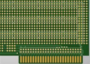
Connection of the PCB Supplier :
The customer may request that some or all of the fire hose are to be plucked with resin and capped over with Copper IPC 476. one type seven, the ITC via film machine, has a set of vacuum heads that create a localized vacuum the epoxy resin is then pulled into the wires due to a pressure difference this ensures that through. The blind fires can be filled 100% with no voiding; the copper plating is deposited electrically on areas without resistance and within the wires to PCB Supplier to create connections between the inner layers.

The PCB Supplier panel is placed in the plating solution and acts as the cathode side of the plating cell, attracting the Copper. When an electrical current is applied, tin is applied, acting as an etch resist the SES line, or strip edge strip line firstly removes the plating resist exposed and developed in the same way as the inner layer resist. They chemically remove the Copper that was covered by the plating resist. Finally, the tin is removed, protecting the copper image on the surface and in the vial, leaving the required circuitry. The Copper in the via is now connecting all the inner layers to the surface. The outer layers are complete; they repeat the optical inspection process any faulty panels are discarded.
The etched panels finally need to have the copper surface roughened and done chemically through the m e CH line. Once the panels have been through the line, they are run through a technical roller to remove any food. The entire panel is coated in a solder mask using a spray or screen print process and dried in a tunnel oven. The panel is then imaged through a mask of black and clear using UV light areas. Where the mask isn’t required solder of ball pads etc., our masks from UV light, the Schmoll MDI machine can also be used to expose the solder mask.
Process of the PCB Supplier :
This is used when very fine apertures or tight alignment is required, generally for small BGA component Footprints. The indent or notation is added to the board using a Semi-automatic printing process. the text is applied over the solder mask cured with the UV light and then inspected to ensure correct alignment and a crisp, legible image. Finally, the board is baked a surface finish is applied to the exposed copper areas left by the solder mask process. This finish is used to protect the Copper and aid the Solder ability properties of the finished PCB.
All PCB Supplier boards are inspected under magnification and run through the XRF machine to verify the thickness of the surface finish; this is a non-destructive test using a specific IPC coupon feature. The test ensures all circuits meet our customers’ requirements, industry specifications, and Merlin circuit technology standards. An electrical test uses a flying probe to check for open or short circuits. Every net is tested, and the results are automatically verified against the customer-supplied or generated netlist. Thus, Merlin uses horizontal and vertical test machines to ensure the bare PCB is functioning as the customer requires.
The panels are now routed to a specific shape specified in the manufacturing data. Depending on the customer’s requirements, the panel can either be scored or routed. The QA lab will perform various physical checks on the finished circuit board to ensure it meets the customer’s specifications. The solder ability of the board is checked to verify the board soldiers correctly. Whatever the final finish, this is checked and fired with a rotary solder dip method. Micro sections are created using an automatic grinder and polisher; the section is ground. The center of the required fire allows the IPC-trained engineer to inspect the internal of the board under high magnification for any manufacturing. The results of the micro section and other tests within the QA lab Panels are generated at this stage.

